Design-Led Project Delivery
From Feasibility Study to
Operational Handover
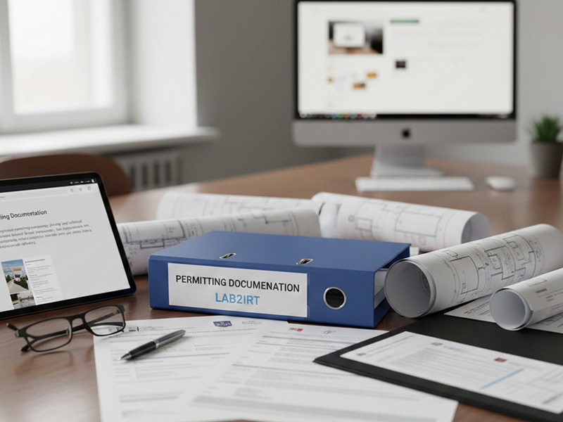
A structured, transparent process designed for institutional clients, with permitting documentation, environmental integration, and ongoing support built in from day one.